|
This page describes the construction of our dearly departed Carbon Fiber composite arms. We miss them.
Building an arm for a torsion machine this large has been very challenging.
A list of our failures in this area might provide
some hints on what not to do.
Our latest arms are made from some high tech stuff provided by
Custom Composite Technologies Inc.
This would not have been possible without Steve's help!
 Steve cuts open our old fiberglass arms to figure out what was in them. This gave him a good sense on
what was needed to break them.
Steve cuts open our old fiberglass arms to figure out what was in them. This gave him a good sense on
what was needed to break them.
The core of our arms are made of three key pieces.
 The ash core was made out of many pieces of 1" rough cut ash planks. These were planed down, fitted together and then
screwed together. The dry block then had a V notch cut out of it.
The ash core was made out of many pieces of 1" rough cut ash planks. These were planed down, fitted together and then
screwed together. The dry block then had a V notch cut out of it.
The dry boards were then unscrewed, cleaned, and sorted. Stiff steel rods (1/8" diameter) were then used through the screw-holes
to line everything up during the gluing and setting process.
The purpose of the ash core is to provide lots of impact strength in the base of the arm where it strikes the stanchions. The base
of the V notch sits outside the impact zone. Another purpose of the ash is to prevent the rope bundles from crushing the arm.
 Foam cores made from 7lb density atc foam stretch away from the ash cores. Unlike our
last set of arms this foam will add to the strength and stability of these arms.
Foam cores made from 7lb density atc foam stretch away from the ash cores. Unlike our
last set of arms this foam will add to the strength and stability of these arms.
Next to these foam cores you can see a 2" carbon-fiber pipe. This pipe was bonded onto the tips of the arms. It will later hold our bowstring pin in place.
 The foam layers were bonded together, then split in the opposite direction. The original layering was done for ease of creating a taper.
The split was to put an I (as in an I-beam) in the direction of load. The flange in the eye is made of 34oz stress quad fiberglass and a single
layer of hardwire. The hardwire is there to hold the arm together if they break, though they would likely not shatter in pieces without it either.
The foam layers were bonded together, then split in the opposite direction. The original layering was done for ease of creating a taper.
The split was to put an I (as in an I-beam) in the direction of load. The flange in the eye is made of 34oz stress quad fiberglass and a single
layer of hardwire. The hardwire is there to hold the arm together if they break, though they would likely not shatter in pieces without it either.
In this picture, you can see the bonding layers between the originally cut foam slabs. In the blue release, you can see dent from the I beam flange.
In the background you can see Dave explaining things to the camera man who came to film the adventure.
 The ash core was bonded to the foam using cabasil and a brown thickener. A messy process that resulted in many a chocolate frosting joke.
 The carbon fiber tube was also glued in the same way. (The black bit at the end of the arm here.)
Kevin was charged with tracking the temperature as the resin in the bonding agent cured, holding the tube onto the end of the foam.
After the core had been bonded together and had a chance to cure over lunch, it was time to wrap the whole thing.
 First the raw materials had to be shaped and organized. here Roger is cutting out 25' long strips of carbon fiber uni. Three strips of these
were wrapped over each arm.
First the raw materials had to be shaped and organized. here Roger is cutting out 25' long strips of carbon fiber uni. Three strips of these
were wrapped over each arm.
 Those strips, plus big sheets of biaxial carbon fiber were then bagged, and pre-wet with resin. This makes sure that the resin completely permeates
between all the different fibers in these sheets. Air bubbles can cause small weaknesses in the fabricated beam.
Those strips, plus big sheets of biaxial carbon fiber were then bagged, and pre-wet with resin. This makes sure that the resin completely permeates
between all the different fibers in these sheets. Air bubbles can cause small weaknesses in the fabricated beam.
 Roger also spent a lot of time measuring and cutting long strips of kevlar. This kevlar is destined to provide extra durability and resilience to
the arm.
Roger also spent a lot of time measuring and cutting long strips of kevlar. This kevlar is destined to provide extra durability and resilience to
the arm.
Again, the cameraman was taking lots of video of the arm fabrication process.
 The completed arm cores were then sanded down, cleaned up, and here Steve applies a layer of resin onto the arms for the very first wraps.
 The first wrap of biaxial carbon fiber goes on. These large sheets wrapped the entire arm.
 The long strips of carbon fiber were then brought over, and carefully placed over the load bearing surfaces.
After that, 12 short strips of uni were wrapped at a bias around the arm to add sheer strength the the top and bottom.
The long strips of carbon fiber were then brought over, and carefully placed over the load bearing surfaces.
After that, 12 short strips of uni were wrapped at a bias around the arm to add sheer strength the the top and bottom.
 After the arm was wrapped a second time in biax, the Kevlar was then spiraled around the arm. This adds more sheer strength
onto the webs of the arms, and improves the resilience from striking forces.
After the arm was wrapped a second time in biax, the Kevlar was then spiraled around the arm. This adds more sheer strength
onto the webs of the arms, and improves the resilience from striking forces.
 After they were all done being made, the arms were put into bags, and placed under vacuum. The vacuum pulls out any air and excess resin
that ended up on the arms after this process. It also compresses the fibers together, which lets them be much stronger.
After they were all done being made, the arms were put into bags, and placed under vacuum. The vacuum pulls out any air and excess resin
that ended up on the arms after this process. It also compresses the fibers together, which lets them be much stronger.
 The arms were then baked under electric blankets overnight. Putting them under heat helps cure the resin which can have a long
working time. Without the heat, they may have still been sticky in the morning.
The arms were then baked under electric blankets overnight. Putting them under heat helps cure the resin which can have a long
working time. Without the heat, they may have still been sticky in the morning.
 The bags then had to be removed, and the release, and special absorptive cloth had to be removed using manly methods of hammer and crowbar.
Beneath the golden hue of ballista arm perfection peaked out.
The bags then had to be removed, and the release, and special absorptive cloth had to be removed using manly methods of hammer and crowbar.
Beneath the golden hue of ballista arm perfection peaked out.
 The first part of arm construction is complete. Steve, Roger and Eric hold up one of the arms.
While the arm fabrication process was super cool and complicated, getting the bowstring attachment points molded in proved to be a challenge.
We had to fabricate new aluminum pins that go through the carbon-fiber tube, and also reinforce the tips to distribute the point-load.
 First, the arm tips were smoothed out with cabasil, and then pads of carbon fiber are added onto the tips.
 Next, the material rough bits were sanded off, and a hole was cut into the tube we had inserted earlier. A router flushing bit was used
against the inside edge of the tube to make sure we had a nice clean and round path through the arm.
Next, the material rough bits were sanded off, and a hole was cut into the tube we had inserted earlier. A router flushing bit was used
against the inside edge of the tube to make sure we had a nice clean and round path through the arm.
 A new pin made by Jeff was then centered into the hole, and bonded in with resin. A plug of cabasil was used to keep the resin
from leaking out the bottom.
A new pin made by Jeff was then centered into the hole, and bonded in with resin. A plug of cabasil was used to keep the resin
from leaking out the bottom.
 A few hundred individual carbon fiber threads were then pulled out of some fabric, and carefully organized. Each thread was dipped in resin
to pre-preg it, then carefully wrapped around the pin in the load bearing direction.
A few hundred individual carbon fiber threads were then pulled out of some fabric, and carefully organized. Each thread was dipped in resin
to pre-preg it, then carefully wrapped around the pin in the load bearing direction.
 After the tows were all added, this picture shows them still shiny with wet resin. Here you can see that the tows wrap around the pin, then deviate in slightly different
directions across the arm. This will transfer the pin load across the face of the arm, removing extreme point load. This also means that
the arms can only ever be used in one direction.
After the tows were all added, this picture shows them still shiny with wet resin. Here you can see that the tows wrap around the pin, then deviate in slightly different
directions across the arm. This will transfer the pin load across the face of the arm, removing extreme point load. This also means that
the arms can only ever be used in one direction.
|
Installation of the new arms
|
 Unfortunately, the tight schedule we had to get everything ready for filming for the History Channel
meant the arms were installed into the machine before we were done! Here Kevin is whipping up our last batch of cabasil which was used
to smooth out the arm tips. All that resin and carbon fiber tows caused a bumpy sharp surface which would be vary bad for our bowstring.
Unfortunately, the tight schedule we had to get everything ready for filming for the History Channel
meant the arms were installed into the machine before we were done! Here Kevin is whipping up our last batch of cabasil which was used
to smooth out the arm tips. All that resin and carbon fiber tows caused a bumpy sharp surface which would be vary bad for our bowstring.

The finished product under load.... and in the rain.
While you can see flex in these arms, they are not nearly as bendy as our original fiberglass arms.
You can also see the brownish tips from the cabasil mentioned in the previous image.
Once again: Thank You Steve, of Custom Composite Technologies Inc. for these wonderful
new arms. They work well. Huzzah!
|
Additional Pages for Mista Ballista
|
|
Mista Ballista
|
 Mista Ballista is _Team Tormentum's_ *Torsion Division* competition catapult.
|
|
Mista Ballista : Modiolus and Epizygis
|
 In 2008, Dave devised a new system for managing the torsion in Mista Ballista with his friends Karl Hamm and Kevin Cheney.
This represents a large investment in our machine in these custom parts.
In 2008, Dave devised a new system for managing the torsion in Mista Ballista with his friends Karl Hamm and Kevin Cheney.
This represents a large investment in our machine in these custom parts.
|
|
Mista Ballista : Bowstring
|
 The bowstring has been one of the most challenging pieces of our torsion engine. It is the last piece to get right, and has been the most likely part to fail in any given year.
|
|
Mista Ballista : Rope Bundles
|
 The rope bundles are the main engine of the machine. The framework that holds
everything together is about 24 ft long, and 6 feet tall.
The rope bundles are the main engine of the machine. The framework that holds
everything together is about 24 ft long, and 6 feet tall.
|
|
Mista Ballista : 2005 Rope bundle Upgrade
|
 At the 2004 chunk the main stanchions for the torsion frames were bent by the impact of the arms.
You can see the animation of when this happened on the Mista Ballista Arms page.
At the 2004 chunk the main stanchions for the torsion frames were bent by the impact of the arms.
You can see the animation of when this happened on the Mista Ballista Arms page.
|
|
Mista Ballista : 2006 Rope Bundle Reconfiguration
|
 In 2005 we broke our fancy fiberglass arms. In 2006 we got the new carbon fiber arms
and video taped them in action in the summer at our 2006 History Chunk. This led us to discover how much they bounced around
the outer stanchions. We were getting multiple recoils after every shot, sometimes back at least 30 degrees. That was also just with 2000 lbs of pullback, which is much less than we expect to use in competition.
In 2005 we broke our fancy fiberglass arms. In 2006 we got the new carbon fiber arms
and video taped them in action in the summer at our 2006 History Chunk. This led us to discover how much they bounced around
the outer stanchions. We were getting multiple recoils after every shot, sometimes back at least 30 degrees. That was also just with 2000 lbs of pullback, which is much less than we expect to use in competition.
|
|
Mista Ballista : Frame
|
 The framework for the Ballista had to be built strong enough to resist the pullback, and to hold up
the 2500 pounds we currently estimate of our engine. It must also push it up 16 feet in the air!
The framework for the Ballista had to be built strong enough to resist the pullback, and to hold up
the 2500 pounds we currently estimate of our engine. It must also push it up 16 feet in the air!
|
|
Mista Ballista : Trailer
|
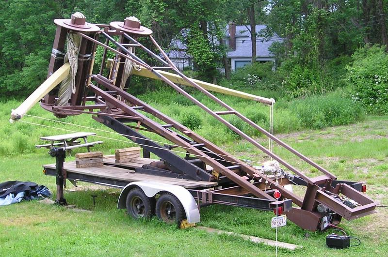
 One of our goals for the 2003 season is to acquire a dedicated trailer for Mista Ballista.
|
|
Mista Ballista : Torsion
|
 Mista Ballista's engine operates on torsion from twisted rope bundles. One of the biggest challenges
of torsion for this machine has been adding the twist. An onager is pretty straight forward in that a large lever and gravity can be used. With our ballista, the direction of twist is sideways, so an alternate means of twisting is needed.
Mista Ballista's engine operates on torsion from twisted rope bundles. One of the biggest challenges
of torsion for this machine has been adding the twist. An onager is pretty straight forward in that a large lever and gravity can be used. With our ballista, the direction of twist is sideways, so an alternate means of twisting is needed.
|
|
Mista Ballista : Arms
|
 After the failure of our arms in 2007, a new tactic was needed. Dave contacted his friends Karl Hamm and Kevin Cheney about designing
and building a set of ballista arms out of aluminum. Aluminum was chosen for its strength and light weight.
After the failure of our arms in 2007, a new tactic was needed. Dave contacted his friends Karl Hamm and Kevin Cheney about designing
and building a set of ballista arms out of aluminum. Aluminum was chosen for its strength and light weight.
|
|
Mista Ballista : Deployment
|
 To travel to different chunkin' locations, we need to pack the system down onto our trailer.
Deploying from the folded up position is challenging and time consuming, taking a day and a half
at the 2002 chunk. This year at the 2003 Punkin Chunk, we were done in about 4 hours.
To travel to different chunkin' locations, we need to pack the system down onto our trailer.
Deploying from the folded up position is challenging and time consuming, taking a day and a half
at the 2002 chunk. This year at the 2003 Punkin Chunk, we were done in about 4 hours.
|
|
Mista Ballista : Hydraulic and Electric Power
|
 Mista Ballista uses hydraulics for lifting the engine to a 45 degree angle for firing, and also for winding the cord bundles.
We also like having electricity on hand since Mr. B has a tendency to break, and need on-field repairs. This page describes
what we are using to power up the system.
Mista Ballista uses hydraulics for lifting the engine to a 45 degree angle for firing, and also for winding the cord bundles.
We also like having electricity on hand since Mr. B has a tendency to break, and need on-field repairs. This page describes
what we are using to power up the system.
|
|
Mista Ballista : Mystery Parts
|
 All winter during 2003 we have been collecting the parts we need to accomplish our 2003 chunk goals.
Here are a bunch of pictures of these random parts. Can you guess what they are for?
All winter during 2003 we have been collecting the parts we need to accomplish our 2003 chunk goals.
Here are a bunch of pictures of these random parts. Can you guess what they are for?
|
|
Mista Ballista : Modiolus and Epizygis 2007
|
 This page describes the Modiolus and Epizygis system we used from 2002 through 2007. In 2008 we developed
a new system for twisting up Mista Ballista.
This page describes the Modiolus and Epizygis system we used from 2002 through 2007. In 2008 we developed
a new system for twisting up Mista Ballista.
|
|
Mista Ballista : Torsion 2007
|
 All torsion catapults depend on twisting the rope bundles to create the engine to drive the catapult. Mista Ballista went through
many phases as we attempted to add more power every year to our throw. This page describes the obsolete systems
we'd used in the past.
All torsion catapults depend on twisting the rope bundles to create the engine to drive the catapult. Mista Ballista went through
many phases as we attempted to add more power every year to our throw. This page describes the obsolete systems
we'd used in the past.
|
|
Mista Ballista : Arms 2006 - 2007
|
This page describes the construction of our dearly departed Carbon Fiber composite arms. We miss them.
|
|
Mista Ballista : Failed Arms
|
 Building an arm for a torsion machine this large has proven to be very challenging.
Based on the experiences of our competitors, who also keep breaking arms, we find that
we are not alone in this dilemma.
Building an arm for a torsion machine this large has proven to be very challenging.
Based on the experiences of our competitors, who also keep breaking arms, we find that
we are not alone in this dilemma.
|
| 