|
The Higgs Throwson started as a rough pencil diagram, and a pile of lumber, and some loose promises from my neighbors to help out.
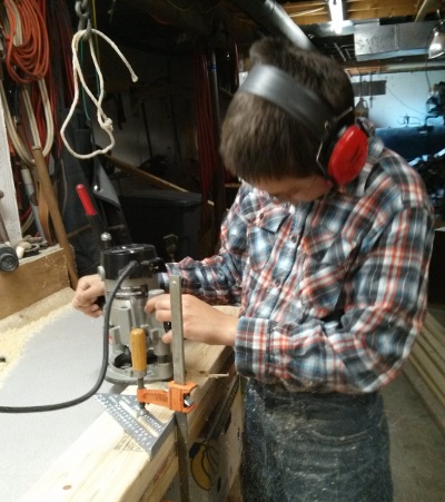 The base of the trebuchet was made with 2x4 with rabbit joints joining them together. We made the rabbits by clamping all the base timbers to a workbench, mapping out where they are to be cut, and routing them out.
This technique made certain that all the rabbits lined up, and that the base would be square. In this image, my son is now old enough to start wrangling the router, and makes lost of sawdust.
The base of the trebuchet was made with 2x4 with rabbit joints joining them together. We made the rabbits by clamping all the base timbers to a workbench, mapping out where they are to be cut, and routing them out.
This technique made certain that all the rabbits lined up, and that the base would be square. In this image, my son is now old enough to start wrangling the router, and makes lost of sawdust.
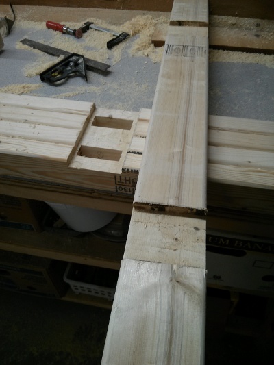 Here you can see one of the feet (on top) with rabbits cut out over the main bottom frame beams with matching rabbits. There are four main beams because we glued 2 2x4s together into a 4x4, so the 4 beams
become two beams. This made cutting the mortises in the main beam super-easy since they were made as rabbit joints, but become mortises when the 2 halves are glued together.
Here you can see one of the feet (on top) with rabbits cut out over the main bottom frame beams with matching rabbits. There are four main beams because we glued 2 2x4s together into a 4x4, so the 4 beams
become two beams. This made cutting the mortises in the main beam super-easy since they were made as rabbit joints, but become mortises when the 2 halves are glued together.
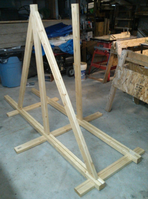
 Once all the base beam mortises were cut, the main upright got a tenon joints added to the bottom, and the side angle supports also got tenons cut on the bottom. All the base tenon and mortise locations were easy to calculate and put in, and the pieces fit like a dream. On the angled pieces, we also placed tenons on the top side, and put this layout together to make sure the mortises in the upright appeared in the correct location.
The upper tenons are much smaller than the lower ones so as to not impinge on the structural integrity of the main upright in the machine.
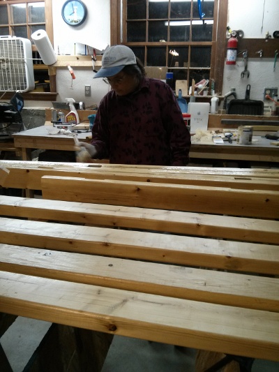 My super awesome wife Amy then sanded and varnished all the wooden parts of the machine.
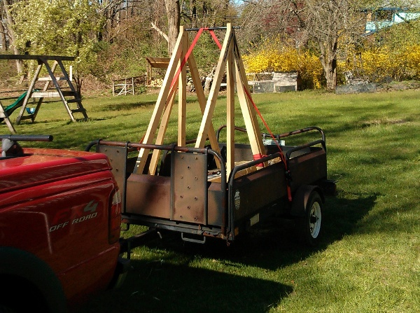
So, having finished fabricating all the individual parts, having never actually assembled the whole thing, how did it go. Here are the steps.
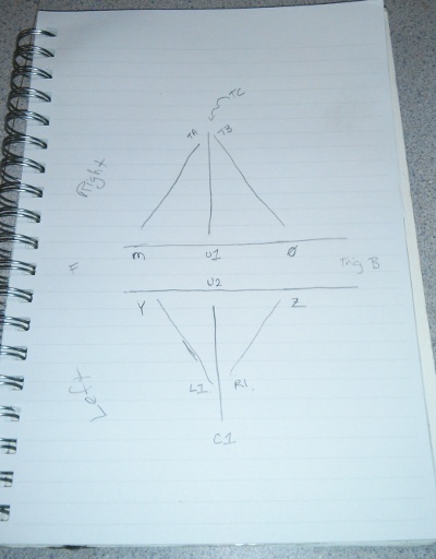 Step 1: Create a joint-map with all labeled joints, and where they belong.
 Step 2: Lay out the 3 feet. Two short feet for the front and back, and the longer center foot that also holds the side supports.
 Step 3: Over lap the rabbits with the main support beams that run back-to-front, mortise side up.
 Step 4: Drop in the uprights, and the front/back supports.
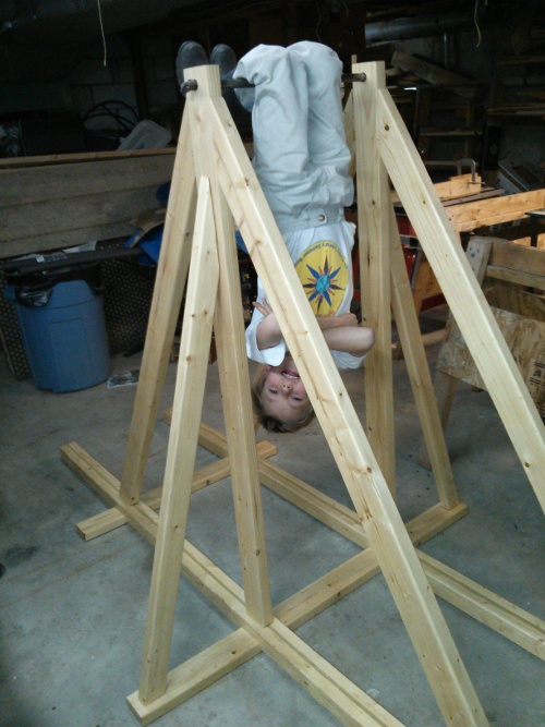 Step 5: Add side-supports and insert fulcrum. Hang child from fulcrum to validate structural integrity.
Note that no screws or glue were harmed in the making of this trebuchet frame.
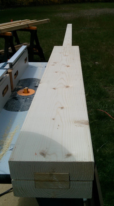 The arm is made of two elements. The first is two furring strips that were run through a jointer, and laminated together. This created a long and relatively strong beam that is very light.
The second is 2 2x6 sections with the centers routed out to fit the laminated furring strips as tightly as possible. The 2x6 pieces add strength between the fulcrum and counterweight.
The arm is made of two elements. The first is two furring strips that were run through a jointer, and laminated together. This created a long and relatively strong beam that is very light.
The second is 2 2x6 sections with the centers routed out to fit the laminated furring strips as tightly as possible. The 2x6 pieces add strength between the fulcrum and counterweight.
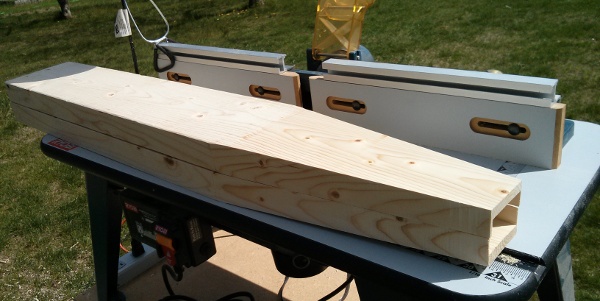 The 2x6 sections were then tapered from around where the fulcrum was to go to the end. The taper prevents a large point-load in the furring strip where the two join.
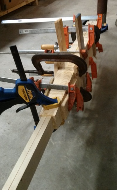 Apply glue and clamps liberally, and let dry. After this, sanding and varnishing.
The counterweight box was built entirely out of steel forged at my neighbor Doug's forge. We started with standard industrial square stock, and turned that into some works of art.
The basic design was pretty simple. One bar would be bent into a U shaped hanger that would hang from the arm. A second bar would be bent into a U shape and disc shaped dumb-bell weights would be
placed over the bar. The two U s would be joined in a plus-shape at the bottom forming a rectangular basket.
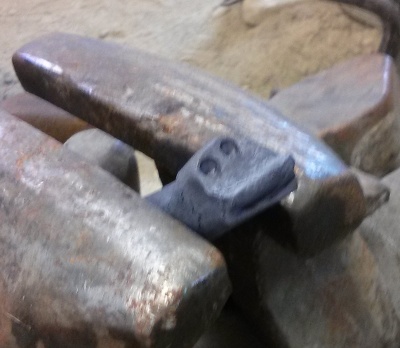
 Here the counterweight bar gets a hole drifted into the center. The hangar bar will be pushed through this hole later.
 Little dragon faces are forged into the ends of the different bars of steel that make up the fulcrum and counterweight box.
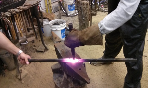
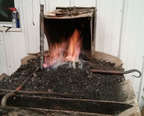 The hanger bar (laying down with the dragon head on the lower left, and tail sticking out on the right) was threaded through the hole drifted in the counterweight holder. This had to be done while the "tail" was still
straight, as we couldn't fit a bend through the hole in the middle. In this image, we are heating up where we will bend the tail to match the bend in the head.
The hanger bar (laying down with the dragon head on the lower left, and tail sticking out on the right) was threaded through the hole drifted in the counterweight holder. This had to be done while the "tail" was still
straight, as we couldn't fit a bend through the hole in the middle. In this image, we are heating up where we will bend the tail to match the bend in the head.
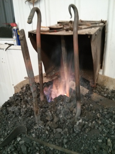 The whole center where the two pieces of steel meat was heated up until it glowed, and then we beat the two pieces together, effectively welding them together.
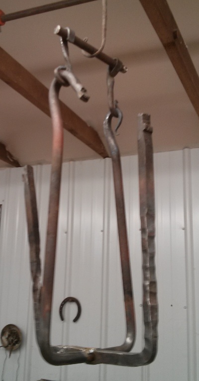 Naturally, the head and tail did not line up. This was expected due to the nature of what we were working with, and our amateur blacksmith status. We made custom hanger loops for each side to make it
balance on our counterweight fulcrum.
Naturally, the head and tail did not line up. This was expected due to the nature of what we were working with, and our amateur blacksmith status. We made custom hanger loops for each side to make it
balance on our counterweight fulcrum.
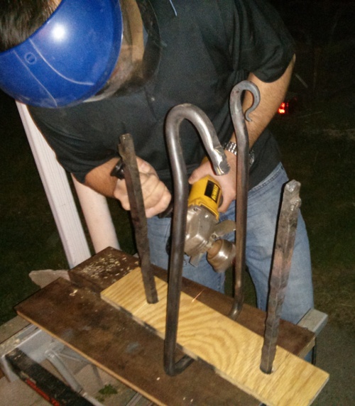 We added a plywood floor to keep the weights from sliding around, and then buffed the dragons until they shined! Here my other neighbor Alex helps out with the wire-wheel cleaning up the metal.
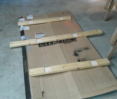
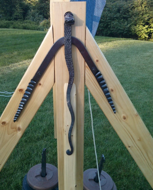
The brackets on the sides of the Higgs are both functional brackets that keep the machine from popping its joints, and decorative 3-part dragons.
The fulcrum has a forged dragon head on each end. There is a tail decoration that connects the side of the main upright to the side-supports, and then wings that grab onto the forward/back support beams.
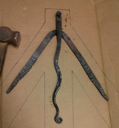 In this image you can see all 3 major parts sitting on a cardboard template tracing I made of the wooden frame.
The forged wing bracket was made out of some flat-bar stock which was tapered out, and 'feathers' were added to the wings.
The tail was also made of flat-bar stock which was tapered, and then made into the twisty tail shape. The very end of the tail will wrap around a screw.
The head of the dragon is the fulcrum of the machine.
In this image you can see all 3 major parts sitting on a cardboard template tracing I made of the wooden frame.
The forged wing bracket was made out of some flat-bar stock which was tapered out, and 'feathers' were added to the wings.
The tail was also made of flat-bar stock which was tapered, and then made into the twisty tail shape. The very end of the tail will wrap around a screw.
The head of the dragon is the fulcrum of the machine.
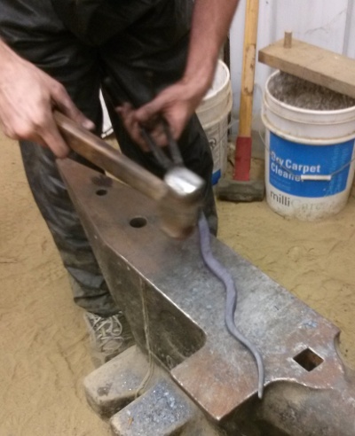 Here's an image of the tail of our dragon being forged. Some bar stock was tapered and lengthened on the anvil, and then given the wavy tail shape.
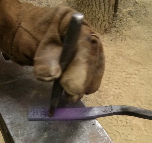 Adding scales onto the tail section with a template punch.
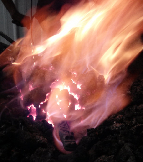 Gratuitous image of the fulcrum with dragon already forged being heated up in an effort to remove some of the rust scale off the main beam.
 After lots of cleanup, and a couple holes drilled, final assembly creates a fine looking dragon holding the machine together.
I consider the dragon to be mainly decorative. The mortise and tenon joints do all the work, but when the machine is rocking around, this little guy helps prevent the tenons from
popping out of the mortises on the top of the machine.
| 
 The Higgs Throwson trebuchet was built to compete at a competition held at the Higgens Armory in Worcester MA.
 This page lists some activities the Higgs Throwson participated in in 2013 after it was built.